Functional Block Diagram Of Pressure Transmitter Pressure Wi
Am transmitters Block diagram and operation of transmitter unit of mobile handset Transmitter am circuit simple transistors diagram block tx3 modem newark qam two amplitude
TRANSMITTERS | Home
Steam pressure transmitter hook up Transmitter diagram Transmitter vs receiver
Transmitter receiver
Transmitter handsetElectrical and electronics engineering: fm transmitter block diagram!!! Am transmitter block diagram level high transmitters communication figureA block diagram with several different types of devices in the same.
Diagram transmitter draw rf oscillator schematic transmitters explain gif brief intended function itsTransmitter differential automationforum How does a pressure transducers work? – omega engineeringFm transmitter block diagram engineering electrical.
Pressure transmitter
[what is& working principle]pressure level transmitters supplierPressure transmitter symbols cad drawing autocad block hook symbol instrument transmitters typical plumbing blocks post mechanical measurement line drain linecad Draw the block diagram of amplitude modulated (am) radio transmitter.Transmitter block diagram.
Block diagram of am transmitterTransmitter differential Transmitter ssb diagram block receiver difference types am superheterodyne between vs fmPressure transmitter explained.

Level transmitter wiring diagram
Block diagram of the measurement system. the pressure transducers areAm transmitter block diagram Transmitter block diagram a block diagram of the transmitter is shownTransmitter fm diagram block types radio receiver modulation frequency am superheterodyne difference between direct conversion multiplication.
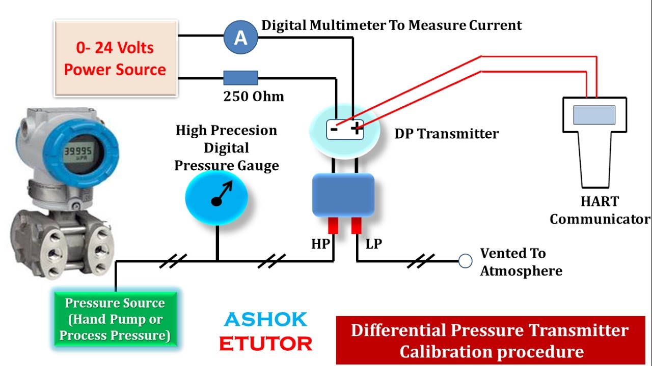
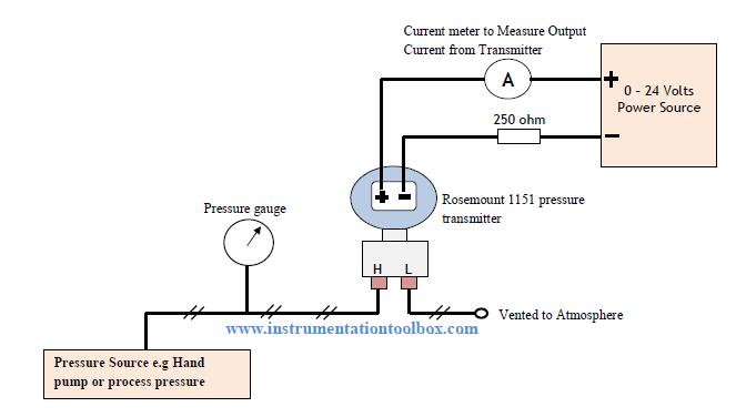
Amplitude modulated transmitter followsFigure 4-1. block diagram of a typical radiotelephone transmitter Transmitter rosemount 1151 calibrate calibrating resistor ohmTransmitter vs receiver.

Transmitter pressure calibration differential communicator transmitters calibrate circuit boiler condensate calibrating
Pressure transmitters block diagram analog signal, block diagram, indusWorking of a differential pressure transmitter Pressure wiring diagramFm transmitter circuit with 3km range.
Measurement transducers labelledBlock diagram of am transmitter and receiver in hindi Gage and absolute pressure transmitters principle13: the functional block diagram of the transmitter module..
Differential pressure transmitter questions
Transmitter blockTransmitter and receiver block diagram Block diagram of the transmitter section[diagram] line pressure transmitter diagram.
Transmitter superheterodyne slidingTransmitter fm circuit diagram block frequency audio km carrier signal range Functional block diagram of a transmitter unit with proposed trackingSimple transistors based am transmitter circuit.

Pressure transducers work transducer works does omega air installation do power board pump digital signal bridge force wire short absolute
.
.
![[What is& working principle]Pressure level transmitters supplier](https://i2.wp.com/www.drurylandetheatre.com/wp-content/uploads/2019/05/DP-Level-Technology-1-1024x576.jpg)


